Superposition Theorem Solve a Linear DC Network
Kirchhoff’s voltage law can be used to analyze any electric circuit but when dealing with complex circuits, using Kirchhoff's voltage laws can be difficult. Therefore, it is important for you to learn other network theorems and recognize when to apply them. In this blog, we will be discussing Superposition Theorem. Superposition theorem can be used when trying to analyze a linear circuit with multiple voltage and current sources. It is important to note, that the superposition theorem can only be used for linear circuits, if there are non-linear components such as capacitors or inductors, the superposition theorem cannot be used.
Superposition theorem states that the current that flows at any point in a circuit, or the potential difference between any two points in a circuit, resulting from more than one source of voltage connected in the circuit, is the algebraic sum of the separate currents or voltages at these points. This means, when a circuit involves multiple voltage and current sources, you treat each source as an independent source and calculate the voltage and current that the sources have on the circuit and then combine the voltages or currents together.
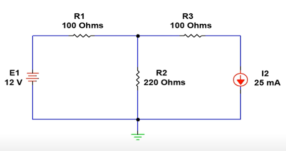
To understand this concept, we will divide the superposition theorem into 6 steps and use it to analyze and calculate the total resistor voltage and current of a simple two-source linear DC Network shown in Figure 1.
Steps For Using Superposition Theorem
Step 1: Identify all the voltage and current sources in the network.
In this circuit, there is a 12 V voltage source and 25mA current source.

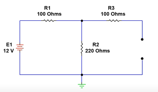
Step 2: Isolate a single source.
Eliminate all but one source and analyze the circuit. When you eliminate a current source, it acts as an open circuit and when you eliminate a voltage source, it acts as a short circuit. In this example, we will eliminate the current source and analyze the circuit with just the 12 V voltage source as shown in Figure 3.
Step 3: Calculate resistor currents produced by the voltage source.
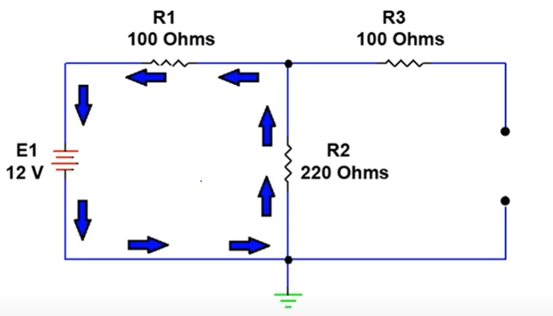
Using Ohm’s Law, we can calculate the individual currents flowing through each resistor. Note that due to the open circuit no current will be flowing through R3 of Figure 4.
For source E1:
Rt = R1 + R2
Rt = 100 + 220
Rt = 320 Ohms
IR1 = IR2 = E1 / Rt
IR1 = IR2 = 12 / 320
IR1 = IR2 = 37.5 mA
IR3 = 0
Step 4: Repeat steps 2 and 3 for the rest of the sources.
Now eliminate the voltage source and replace it with a short circuit as shown in Figure 5 and calculate resistor currents based on the I2 current source.
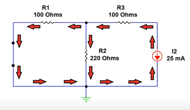
We will use the current divider rule to calculate the current through individual resistors.
For Source I2:
IR3 = I2 = 25 mA
IR1 = IR3 * [R2/ (R1+R2)]
IR1 = 25 mA * [220 Ω/ (100+220) Ω]
IR1 = 17.1875 mA
IR2 = IR3 – IR1
IR2 = 25 mA – 17.1875 mA
IR2 = 7.8125 mA
Step 5: Sum the current of each source together.
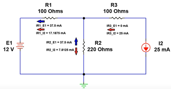
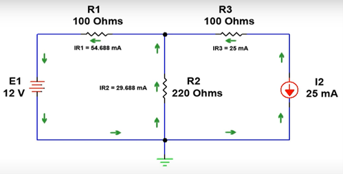
Having obtained the resistor currents for each individual source in the network, we combine the results to arrive at the net resulting resistor currents as shown in Figures 6(a) and 6(b).
|
For Source E1
|
For Source I2
|
|
IR1 = 37.5 mA |
IR1 = 17.1875 mA |
|
IR2 = 37.5 mA |
IR2 = 7.8125 mA |
|
IR3 = 0 mA |
IR3 = 25 mA |
If the individual resistor currents flow in the same direction they are summed or added, and if they flow in the opposite direction they are subtracted. We now know the net resulting current magnitude and direction for all points in the circuit.
|
Net Resulting Resistor Currents |
||
|
IR1 = IR1_E1 + IR1_I2 |
IR2 = IR2_E1 – IR2_I2 IR2 = 37.5 mA – 7.8125 mA |
IR3 = IR3_E1 + IR3_I2 |
Step 6: Calculate the voltage on each resistor
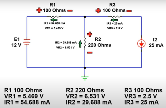
Since we know the magnitude and direction of the net resulting current flowing through each resistor, we can use Ohm’s law to calculate the voltage drop across each resistor.
VR1 = I1*R1
VR1 = 54.6875 mA*100 Ohms
VR1 = 5.469 V
VR2 = IR2* R2
VR2 = 29.6876 mA* 220 Ohms
VR2 = 6.531 V
VR3 = IR3*R3
VR3 = 25 mA * 100 Ohms
VR3 = 2.5 V
We can determine the polarity of the voltage drop across each resistor by observing the net resulting current directions and we can complete the analysis for each component of the network as shown in Figure 7.
To summarize, the superposition theorem states that a circuit can be analyzed with only one source of power at a time, and the result of each source is then combined to find the total response of the circuit. As seen in this discussion, the superposition theorem is a powerful tool when analyzing linear DC networks with multiple sources.
We hope this has been helpful to you as a technician or a student entering the field. If you have any questions about the Electronics Technician programs you can reach one of our Program Consultants toll-free at 1-888-553-5333 or by email at [email protected].
Comments
Very informative
Submitted by Ogede Rosemary… (not verified) on Wed, 10/09/2024 - 19:08
Thank you for this beneficial explanation, it gave me a good understanding of the topic.
Well explained
Submitted by Mustapha yusuph (not verified) on Fri, 11/01/2024 - 02:13
Well explained
your explanation makes it…
Submitted by mr Maniii (not verified) on Mon, 04/21/2025 - 06:07
your explanation makes it easy to understand this theorem ,thank you
super_position theorem in dc circuit