Everything you need to know about current divider circuits
In this blog we will review the theory of the Current Divider circuits in a parallel circuit. In a parallel circuit, all the components have their terminals connected together sharing the same two end nodes. This results in different paths and branches for the current to flow or pass along. However, the currents can have different values through each component but the voltage remains the same across two end nodes.
Resistive Current Divider Circuits
Consider a current divider circuit with two resistors connected together in parallel as shown in below diagram. We will explain how to calculate the current flowing through each resistor in a two or more resistor parallel circuits. Parallel resistors R1 and R2 splits the supply or source current between them into two separate currents IR1 and IR2 before joining together again and returning back to the source.
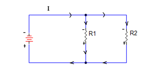
As the total current equals the sum of the individual branch currents, then the total current, IT flowing in the circuit is given by Kirchhoff’s current law(KCL) as:
IT = IR1 + IR2 …………….............. Equation 1
As the two resistors are connected in parallel, for Kirchhoff’s Current Law, (KCL) to hold true it must therefore follow that the current flowing through resistor R1 will be equal to IR1 = IT – IR2
Similarly, current flowing through resistor R2 will be equal to IR2 = IT – IR1
Let’s calculate voltages; V1= IR1 X R1 & V2= IR2 X R2
Since the Voltage across each resistor is same IR1 = V/R1 and IR2 =V/R2
Substituting IR1 and IR2 in Eq (1); we now realize that IT = V[(1/R1)+(1/R2)]
re-arranging this we get V= IT [(R1 X R2)/(R1+R2 )]
Solving for IR1 gives: IR1 = IT (V/R1) = IT [R2/(R1+R2)]
Likewise, solving for IR2 gives: IR2 = IT [R1/(R1+R2)]
Notice that the above equations for each branch current has the opposite resistor in its numerator while solving for I1 we use R2, and to solve for I2 we use R1. This is because each branch current is inversely proportional to its resistance.
Current Divider Practice Example 1:
Assuming a total current of 25mA flowing through the network. Resistor R1=6 and R2=9 is connected in parallel. Let us find out IR1 & IR2 using above concept.
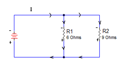
How to find IR1 & IR2 ?
IR1 =  =
=  =
=  = 15mA
IR2 =  =
=  =
=  =
= = 10mA
Current Divider Circuit with Three Or More Parallel Branches
In the case of three or more parallel branches, the equivalent resistance is used to divide the total current into the fractional currents. The total current, IT being the sum of all the individual branch currents. IT = IR1+ IR2+ …. + IRx
Using the same concepts above, I Rx =  ; where x = 1,2,3,4 and RT = R1+R2+….+RN
We hope this has been helpful to you as a Technician or a student entering the field. If you have any questions about the Electronics or the Electromechanical Technician programs you can reach one of our Program Consultants toll-free at 1-888-553-5333 or by email at [email protected].