The Utility of Finding the Thevenin Equivalent Circuit
In this installment of our "Practicing Technician" series, we will once again be working with a circuit reduction technique. This particular technique is quite useful for determining how changes in load conditions can impact on circuit performance. Until now, we have provided reduction techniques that are useful for fixed load circuit analysis. Thevenin's theorem can be used in cases where we want to see how load voltage, current and power are effected by changes in load resistance.
As an example of the utility of this theorem consider the testing of any power generation equipment. One of the key aspects of such a test exercise illustrates the usefulness of being able to make multiple calculations pertaining to varying load conditions easily. A resistive or unity power factor load bank is a device that is designed to provide scalable loads and is used during testing of power generation equipment. To calculate expected values under the relevant series of load conditions can be tedious. Thevenin's circuit reduction approach simplifies it. Not only can this approach be applied to larger scale power generation applications, it applies to something as simple as testing automotive batteries for high load usage during the turning over of the engine as opposed to other expected operating conditions

How is this useful?
The theorem can be applied to create a simplified version of a linear DC network that consists of only a single source and series resistance which will behave identically to the linear DC network in terms of the load. As an example, this would drastically reduce the number of calculations required to obtain data in a situation where we want to know how a given network responds to 50%, 60%, 70%, 80% and 90% full load conditions. A somewhat complex traditional Loop or Nodal analysis would need to be repeated 5 times to make the data available for each load value. As an alternative, we can create a Thevenin Equivalent circuit consisting of a single source and series resistance that will behave identically with respect to the load as the entire linear DC network would, and then do 5 very simple ohm’s law level calculations to acquire load voltage (current, or power) under each load condition.
In this example, it is easy to see how the reduced circuit representation (bottom) can simplify our desired calculations for different loads even for a linear DC network as simple as the one used here which consists of only a single source and 4 resistors.
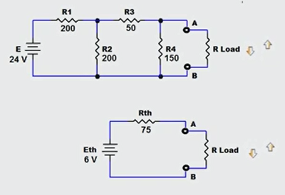
The original network (top) is quite simple, however, with Thevenin circuit reduction, the equivalent circuit (bottom) is much easier to work with when you need to know load voltage and load current for loads of 50 ohms, 60 ohms, 70 ohms, 80 ohms, and 90 ohms. With the reduced version, you can use V/R to find load current, and a simple voltage divider to calculate load voltage for each load resistance value. In contrast, if you use Loop or Nodal analysis, you would need to repeat those complex calculations over and over to get the desired data.
This powerful technique is not restricted to only simple single source linear DC networks. It can be used on multi-source, complex networks as well. The move complex your original linear DC network is, the more you simplify your life by creating the Thevenin Equivalent circuit representation of that network.
What does the theorem state?
A two-terminal linear DC network, consisting of any number of fixed value resistances and any number of fixed DC voltage and current sources, can be replaced by a single voltage source in series with a single resistance that will produce the same effects at the terminals.
How is it implemented?
Essentially, we redraw the circuit to provide a simplified version that behaves identically.
Step 1: Identify the portion of the network for which you require the Thevenin Equivalent circuit. Label the two terminals as points A and B and remove the portion not being included in the reduction. (ie. the load)
Step 2: Determine the Thevenin equivalent resistance (Rth) by short circuiting all voltage sources, and open circuiting all current sources. Once done, calculate the resistance that now appears between the two terminals labelled points A and B.
Step 3: Determine the Thevenin equivalent voltage (Eth) by returning all sources to their previous position and state, and calculating the voltage that would appear across the two terminals labelled points A and B.
Step 4: Draw the Thevenin Equivalent circuit using a single voltage source with a voltage value of Eth, and a single series resistance using a resistance value of Rth obtained above. Connect the previously removed portion of the circuit (the load) and make your simplified calculations for voltage, current, or power.
In the video below I walk through the process step by step with a simple example. This technique can be very practical when working with varying load applications and I highly recommend becoming familiar with this approach as it can be a massive time saver when applied in the appropriate circumstances.
If you liked this post, check out our previous articles in The Practicing Technician Series;
Using the Natural Log or “ln” Function in Circuit Analysis
How to Create Correct Ohm's Law KCL Branch Equations for Nodal Analysis
How to Solve Simultaneous Equations with Multiple Unknowns
Converting Parallel RL Circuits to their “Easier To Work With” Series Equivalents
Common Rules For Weighted Number Systems
We hope this has been helpful to you as a practicing or student technician. We are looking for other ideas for this continuing Practicing Technician series. Please let us know what you would like us to write about by sending us your thoughts and questions at [email protected].